Fugue Devlog 20: Merging Textures in Blender
At the end of the last post I mentioned some optimization considerations for Fugue’s character models. I managed to reduce the poly count of the human model a bit, but my quick-and-dirty approach (using Blender’s Decimate) messed up the mesh’s structure too much and caused some issues, so I’ll have to try a more manual method [Update: see the end of this post].
The other bit of optimization I started working on was reducing draw calls. A fully dressed character model has several different materials: one for the human (the skin texture) and then one for each item of clothing. I couldn’t find any clear information about how Godot handles draw calls and materials but generally more materials means more draw calls. So if I can merge the skin and clothes materials I should be able to reduce draw calls to as low as one per character.
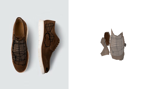
I thought there’d be a Blender addon that does this but I surprisingly couldn’t find any. There are texture atlas baking addons which isn’t quite what I’m looking for–they assume that your UV maps neatly laid out, without overlaps, and they’re usually for baking environmental influence (e.g. lighting/shadows) into the texture (I just need to cut and rearrange the original texture data). Merging materials in the way I have in mind is tricky because each mesh has its own UV map and when you merge the meshes these UV maps all overlap:
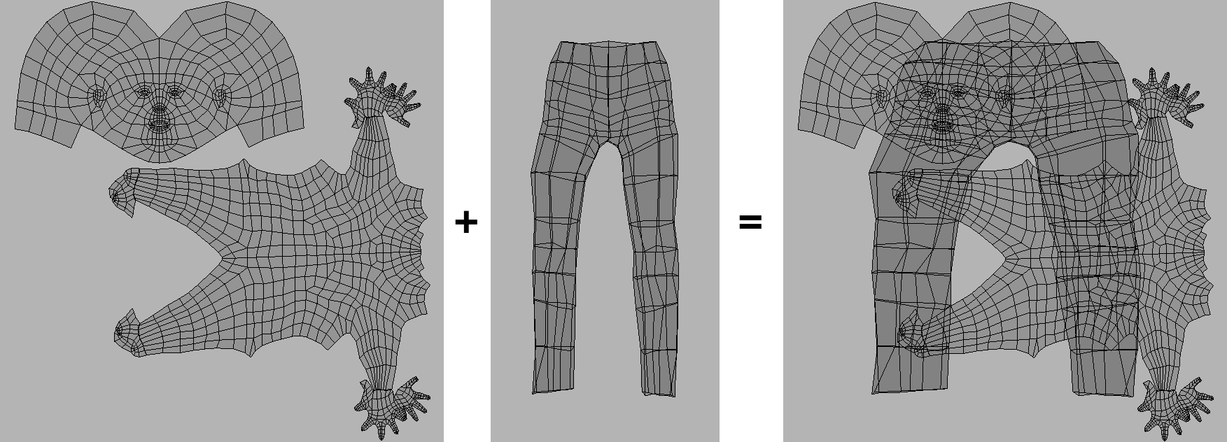
(You can also see that there are some scaling issues, where the pants UV layout is now stretched–the original pants texture has a non-square aspect ratio.)
To solve this you need to scale/move the UV maps so they each have their own space, which then requires you to also move the underlying parts of their original textures to where their UV map regions were moved to so that the correct image data is still mapped to the correct faces.
In theory this isn’t too difficult–there are some tricky parts like placing the UV map regions (a concave bin packing problem) but everything else is straightforward if you have the UV map geometry. But actually implementing this was really rough–probably my most frustrating development experience in recent memory. I’m not even finished yet, so crossing my fingers that nothing else comes up. This is one of those problems that required many different approaches, and it’s possible that I’ll need to pull ideas from old abandoned ideas if I run into new obstacles…so I’ll try to document my thinking and attempts here.
The biggest struggle was with Blender itself. Blender is an amazing tool and its scripting capabilites are awesome, but they feel like an afterthought, especially for background mode/headless scripting. It has so many puzzling design decisions, many useful functions don’t have a Python API, and an inconsistent dependency on the UI. There are functions that behave differently depending on what the active window/area is or if you’re in EDIT mode vs OBJECT mode, and if you aren’t running the UI (i.e. running Blender in background mode) some of these functions don’t work at all. So of course the entire script I developed within the UI environment didn’t end up working when I switched to the background mode 🙃.
There are also some strange instabilities and limitations of headless Blender, like I can’t export UV layouts because “the GPU can’t be used in background mode”, but I’m able to render 3d scenes without any problem. I’m sure there’s a good reason. Similarly, for some reason loading JPGs and converting them to RGBA with Pillow segfaults from within the Blender environment but works just fine using Blender’s Python when not running Blender. Fortunately these problems always had a hacky workaround.
There also just isn’t a lot of information about scripting for headless Blender so it was difficult to find answers or discussion when I did run into problems.
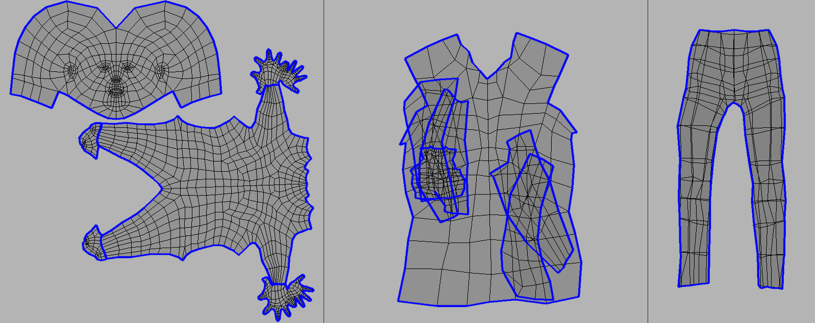
The other difficult part was getting the UV map data I needed–in particular the geometry of each individual UV map region. What I’m calling a “UV map region” here isn’t quite the same as a “UV island”. Islands are sets of connected UVs and they can overlap. In the maps below the islands are outlined in blue:

In my case I care about contiguous regions of UV map, whether or not they are connected. So the UV map on the right with all the overlapping islands would be considered a single UV map region, and each island in the UV map on the left is also its own UV map region.
To identify these regions I needed two bits of information:
- The polygon boundaries of each island
- A mapping of UVs to the island they belong to
Surprisingly there is no built-in Python function to access UVs by island. There is a way to hack it though:
# Make sure the correct object is selected
# and that you're in edit mode
obj = bpy.data.objects['your-object-name']
bpy.context.view_layer.objects.active = obj
bpy.ops.object.mode_set(mode = 'EDIT')
bm = bmesh.from_edit_mesh(bpy.context.active_object.data)
uv_layers = bm.loops.layers.uv.verify()

# Select all UVs
# then generate seams from UV islands
bpy.ops.uv.select_all(action='SELECT')
bpy.ops.uv.seams_from_islands()

# Collect the island boundary edges here
edges = []
for f in bm.faces:
    for l in f.loops:
        if l.edge.seam or l.edge.is_boundary:
            a = l[uv_layers].uv
            b = l.link_loop_next[uv_layers].uv

            # Blender's texture coordinates are flipped
            # than most image processing;
            # i.e. top-left is (0, 1) rather than (0, 0).
            # So we reflect everything over y=0.5 (i.e. flip vertically)
            # to compensate.
            edges.append(((a.x, 1 - a.y), (b.x, 1 - b.y)))
This method relies on Blender’s built in “Seams from Islands” function, which marks the border edges of UV islands as a “seam”. Then we can iterate all edges of the mesh to find those that are marked as a seam.
This actually worked fine until I tried it on a UV map where the seams produced by this function didn’t actually match the island’s borders:
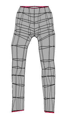
Here the islands, outlined in red, are just the openings of the pants. The rest of the island border isn’t selected.
I didn’t really understand why until I read more on how mesh geometry works in Blender. Meshes are composed of faces, and each face is composed of “loops”. A loop is a vertex and an edge (which connects to another vertex), though I use “edge” and “loop” interchangeably here. Each face has its own loops, even if those edges are shared with other faces. In the example below there are two faces joined by an edge. That edge is actually two edges, one for each face.

From looking at Blender’s source code (at uv_seams_from_islands_exec) I believe the way “Seams from Islands” works is that the UVs for each shared edges/loops are compared; if the UVs aren’t in the same locations then we know that those edges are separate in the UV map, and thus we have the border edge of an island. In the pants example above the parts that aren’t selected aren’t actually separated edges. It’s hard to tell from the image, but they are edges of joined faces that are folded over:

This can also be illustrated by using a graph-based approach for detecting seams:
import networkx as nx

# Same prep as above
bm = bmesh.from_edit_mesh(bpy.context.active_object.data)
uv_layers = bm.loops.layers.uv.verify()

# Collect all edges here
edges = []
for f in bm.faces:
    for l in f.loops:
        a = l[uv_layers].uv
        b = l.link_loop_next[uv_layers].uv
        edges.append(((a.x, 1 - a.y), (b.x, 1 - b.y)))

# UVs don't have any ids;
# we need to know when two UVs are actually the same UV.
# We do this by seeing if two UVs are within some small range;
# if so we consider them to be the same UV.
eps = 1e-6
uv_idx = []
def find_closest(uv: tuple[float, float]):
    x, y = uv
    for i, (x_, y_) in enumerate(uv_idx):
        x_diff = abs(x - x_)
        y_diff = abs(y - y_)
        if x_diff < eps and y_diff <eps:
            return i
    else:
        uv_idx.append(uv)
        return len(uv_idx) - 1

# Reconstruct the UV map geometry
# as a graph.
g = nx.Graph()
for a, b in edges:
    a_id = find_closest(a)
    b_id = find_closest(b)

    # Count how many edges connect
    # these two UVs
    if g.has_edge(a_id, b_id):
        edge = g.edges[a_id, b_id]
        edge['count'] += 1
    else:
        g.add_edge(a_id, b_id, count=1)

# UVs that are connected by only one edge
# are island borders
borders = []
for a_id, b_id, data in g.edges(data=True):
    if data['count'] == 1:
        borders.append((a_id, b_id))
This approach also works on the fact that island borders are separated edges. The general idea is this:
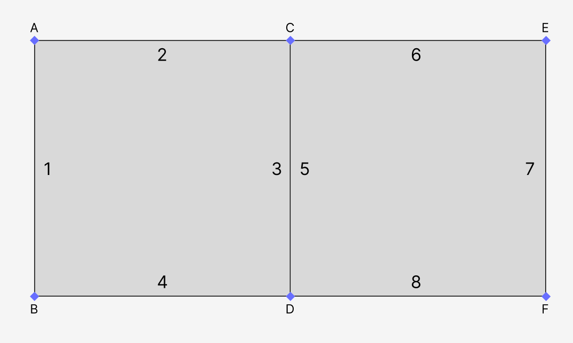
The connection between UVs C and D is not a border because two edges connect them–edge 3 and 5, belong to the left and right faces respectively. The other connections on the other hand have only one edge, and thus they form the island border.
This nice thing about this approach is it’s easy to identify which UVs belong to which islands. With the “Seams from Islands” approach I had a very crude method: just checking which UVs fall within which island polygons. This unfortunately doesn’t work with overlapping islands because the UVs could be assigned to any of the overlapping islands. With this graph-based approach islands are just the connected components of the graph:
uv_ids_to_islands = {}
for island_id, comp in enumerate(nx.connected_components(g)):
    for id in comp:
        uv_ids_to_islands[id] = island_id
However because this is basically the same idea as “Seams from Islands” it suffers from the same issues. The pants UV map would fail in the same way.
The approach I’m using now is less elegant (using graph structures just feels neat) but should work better (I hope):
from collections import defaultdict
from shapely.ops import unary_union
from shapely.geometry import Polygon
from shapely.validation import make_valid

# Same setup as above
bm = bmesh.from_edit_mesh(bpy.context.active_object.data)
uv_layers = bm.loops.layers.uv.verify()

# Here we collect all edges,
# but grouped into their parent faces
faces = []
for f in bm.faces:
    face = []
    for l in f.loops:
        a = l[uv_layers].uv
        b = l.link_loop_next[uv_layers].uv
        if not face:
            face.append((a.x, 1 - a.y))
        face.append((b.x, 1 - b.y))
    faces.append(Polygon(face))

# Group faces into their parent islands
island_faces = defaultdict(list)
for face in faces:
    # Since the UVs are all connected,
    # we can use any UV from the face to identify its parent island
    uv = face.exterior.coords[0]

    # `find_closest` has same definition as above
    # and we still use the graph-based approach
    # for mapping UVs to islands
    uv_id = find_closest(uv)
    island_id = uv_ids_to_islands[uv_id]

    # Fix face geometry as needed
    if not face.is_valid:
        face = make_valid(face)
    island_faces[island_id].append(face)

# Then merge the faces of each island to get
# the island borders/silhouette
island_shapes = []
for island_id, valid_faces in island_faces.items():
    merged = unary_union(valid_faces)
    island_shapes.append(merged)
Here I extract the geometry of every face of the mesh, rather than working with just the edges. I still use the graph-based approach to map faces to islands. Then each island’s faces are merged using shapely and the island’s borders are the exterior of this merged shape.
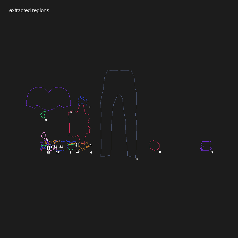
Here are the results of this approach, with the extracted borders in blue:
With the island borders extracted the subsequent steps are a bit easier, which is mainly identifying overlapping islands and merging them into one shape (what I was calling “UV map regions”) and cutting out the matching texture regions.
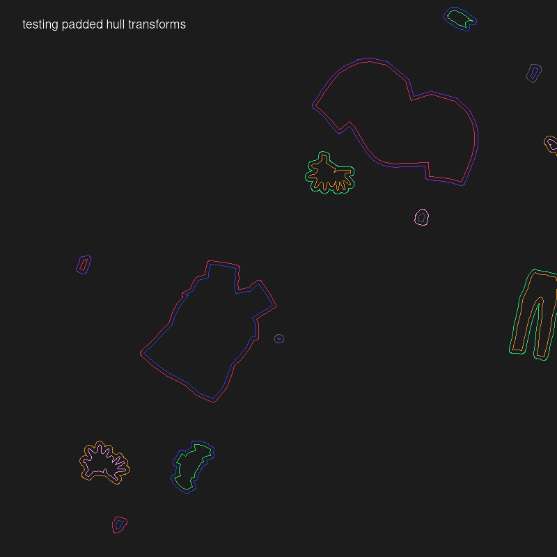
The other important piece is packing these UV map regions. I’m using nest2d, which is a Python interface to libnest2d, for bin packing. There were a couple challenges here too. I’m actually using a fork because the original version bizarrely leaves out a Python API to access the important packing information (translations and rotations of the packed polygons). I also had to expand the Python interface to support some additional libnest2d parameters to avoid packing overlaps. A final adjustment: libnest2d doesn’t support concave shapes so instead of directly using the UV map region polygons I use their convex hulls instead. So the resulting packs won’t be the most space-efficient, but that’s ok.
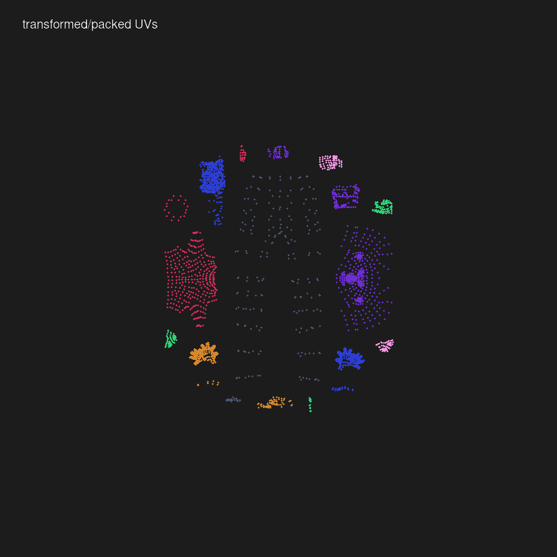
Here are a couple example results from the script:
The full code is available here.
The other component of this system is what handles the actual merging of the Blender objects and materials (merge.py in the code). This was more straightforward: grab the textures for each object’s material (assuming one main material), bin pack them into a single image, and update the UV maps accordingly. Then the packing system described here is applied to the merged object/texture to remove unnecessary image data and the final output is trimmed and/or scaled to be a square texture with dimensions that are powers of 2 (e.g. 512x512, 1024x1024, etc).
The resulting texture for the character I’m working with here:
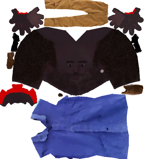
There is some weird artifacting going on; notice the noisy speckled texture on parts of the face and one of the hands. I’m not really sure why that’s occurring, but it’s not especially noticeable, so I won’t worry about it for now.
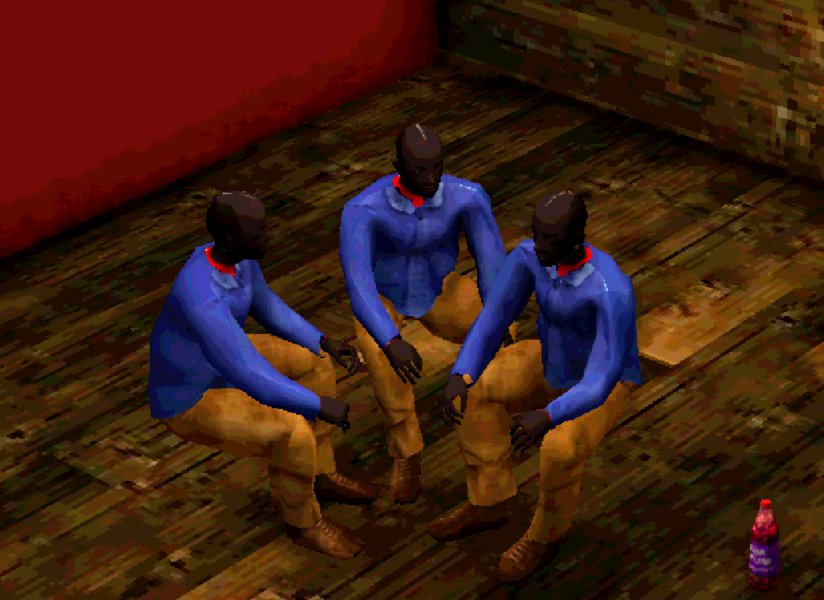
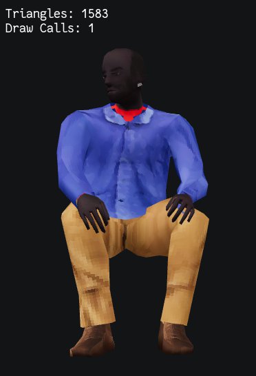
Here we see the draw calls for this character reduced from 4 to 1:

Of course after all of this effort there had to be more problems🙃. The first was a lot of white/blank texture areas showing up in the character. I had thought that this might be an issue–basically extracted textures have no bleed, so if the UV maps aren’t exactly precise then they might cut into empty parts of the texture. The solution to this was to add a padding parameter that provides a few pixels of buffer around each texture clipping.
Yet even after that there was still one other problem. Though the Blender renders and in-browser GLTF preview look fine there is a weird seam that shows up in Godot:
Fortunately this wasn’t too difficult to solve. It was unlikely to be an issue with the exported GLTF itself because the in-browser GLTF preview didn’t have this issue. So it had to be something with Godot. For completeness I’ll go into the details.
When you import an asset into Godot it may process it in some way. For textures this can mean manipulating the images in ways to improve game performance. One such manipulation is the generation of “mipmaps”, which are scaled down versions of the texture to run when the object is at a smaller scale. The problem is that these mipmaps mean that the scaled down textures might not quite line up with the object’s UV maps, which causes texturing bleeding (thus the white line in the render above).
The actual modifications to the imported texture are controlled by default import settings you can define for your project:

That’s how it’s supposed to work, at least. These import settings aren’t respected when importing GLTFs, so I do it manually in my preview script:
# Ensure that mipmaps and filter are disabled
# for each material texture.
# This is because mipmaps can cause issues with bleed,
# i.e. blank parts of the texture bleed through to the UV map.
# For flag values see: <https://docs.godotengine.org/en/stable/classes/class_texture.html#enum-texture-flags>
for child in Util.find_children_of_type(instance, MeshInstance):
    for i in range(child.mesh.get_surface_count()):
        var mat = child.mesh.surface_get_material(i)
        mat.albedo_texture.flags = 0
This works, but then I lose the advantage of mipmaps. There is a clear visual difference between enabling/disabling mipmaps. When turned off the original resolution texture is displayed which can mean showing more detail (I suggest clicking the image to see the full resolution version):
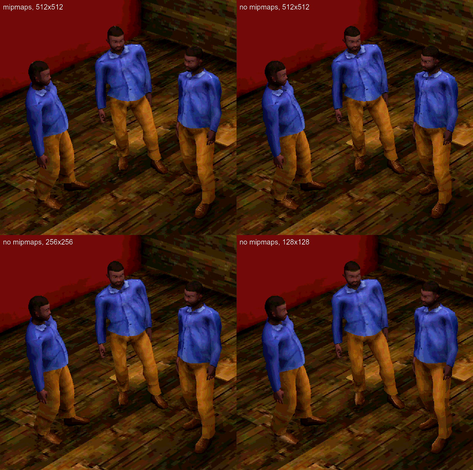
Maybe it’s because I’m used to it now, but the mipmaps version looks better to me. It’s a bit softer and the eyes look better (though I think that’s because I maybe have too bright of a white for the eyeballs). I figured if the lower-res mipmaps version looks better I should just use a lower-res texture to begin with. So I tried downscaling the original 512x512 texture to 256x256 and 128x128 and they both look good. The 128x128 one looks the closest to the mipsmap version, but isn’t exactly the same (Godot may use a different downscaling algorithm; I used Pixeluvo to resize and they don’t say what algorithm they use). Most importantly this manually downscaled version doesn’t have the seam/bleed problem that Godot’s version does. One further issue here is that the 128x128 version does lose some detail–the earrings are much, much harder to see there, so that might be an argument for the 256x256 texture.
This is all a good example of the unexpected and massive diversions that happen with a project like this. I spent so much time and energy on this that could have been spent on more interesting parts of the game. And it’s totally possible that this all just premature optimization. I haven’t developed a game like this so I don’t have any intuition about what I should be focused on for performance. But I really want to avoid the scenario where I’ve generated all this content for the game and then I have to go back and redo everything because of some bad performance decision I made early on (like ignoring draw calls, poly counts, texture sizes, etc).
I don’t think this level of detail is interesting to anyone except me lol. I mostly chronicled this so I have some documentation to refer to when in 3 months I’ve completely forgotten everything and find another edge case that requires me to re-think the whole system (I hope that doesn’t happen, but you never know), but also because maybe there’s some really simple industry standard approach that I completely missed (though I tried to look for one!).
In the end this was one of those things where you’re dealing with two challenges at once: figuring out the high-level algorithm to solve the abstract problem you’re dealing with and figuring out how to implement it in unfamiliar and at times un-/underdocumented or baffingly-designed APIs/libraries. Never a pleasant experience, but I hope it’s worth it!
Update @ 12/9/22 14:30: Right after publishing this I realized that I don’t need to simplify the base human geometry, but only the final geometry that will be exported. Simplifying the base human geometry was hard because of the reasons I mentioned in the last post: meeting the constraints of MakeClothes (quads or tris, minimizing poles) and because simplifying the geometry gives MakeHumans fewer vertices to manipulate the human form with, leading to wonky results. What I’m doing now is throwing a Decimate modifier on as the very last step before exporting the model. This not only simplifies the base human but also any clothes that are attached. At this stage MakeHuman has already done its work, so the constraints of quads/tris and poles no longer apply.
For now I’m using Decimate with a ratio of 0.5, cutting about half of the polys:
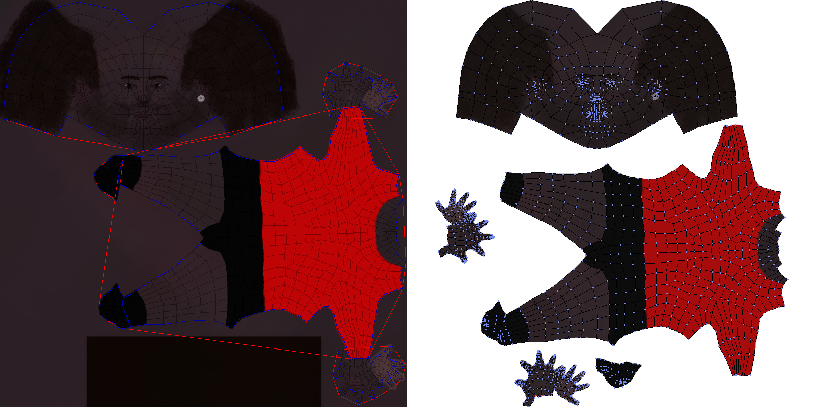
Update @ 12/9/22 22:02: So there was another padding-related bug that was causing textures to overlap after packing them. Basically it came down to the fact that there are three different space systems that are used during the packing process: the UV space (where x and y are both in [0, 1]), the texture space (measured in pixels), and the packing space (which is just a scaled up version of the UV space so that coordinates can be integers). The padding is specified as pixels but I wasn’t properly converting them to the packing space, so I just had to implement the correct conversion.
Here are some images from the debugging process (I thought they looked nice):